
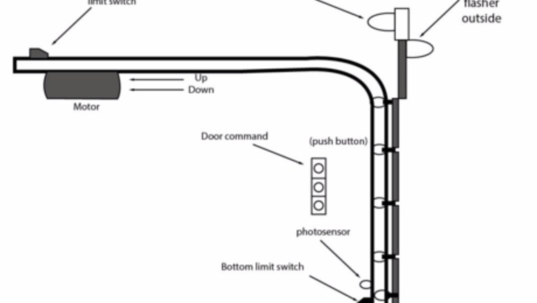
Understanding the Door Layout
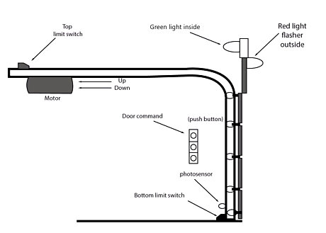
Plan the layout of the design you're building.
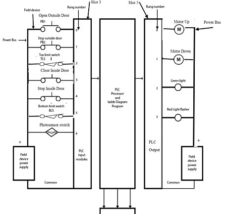
Use the PLC configuration and field device wiring illustrated.
Creating a New Project Using RSLogix 5000
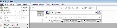
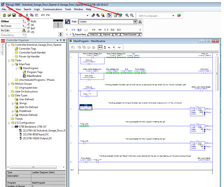
Create a new project named "Industrial Garage Door Opener". Find "Rockwell Software" on your computer. Click on "RSLogix 5000 Enterprise Series" to open a new controller file. Double-click on File to open a new file for the controller. The "File" button is located in the upper left-hand corner of the software.Tenneng 1.png Click and select the CPU type "1756-L62 ControlLogix 5562" from the list.Tenneng 003.png Enter the project name "Industrial Garage Door Opener". Click and select the chassis type "1756-A7 7slot Controllogix 5562" from the list. Select the desired location for your file through Create In. Press OK to complete the project set-up.
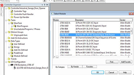
Create the real-world input/output address configuration. Click on Data Types and then add a module to the "I/O configuration". Right click on "New Module" and then click on digital to highlights the modules. Add the Input Module. Click and select "1756-IB16I" from the list. Click OK to open "Input Module Window".Tenneng 04.png Enter the name "Input_DC".Tenneng 005.png Click and select Slot "3" from the list. Click and select "Compatible Keying". Click OK to complete. Add the Output Module. Click and select "1756-OB16I" from the list. Click OK to open "Output Module Window". Tenneng 006.png Enter the name "Output_DC".Tenneng 07.png Click and select Slot "5" from the list. Click and select "Compatible Keying". Click OK to complete.
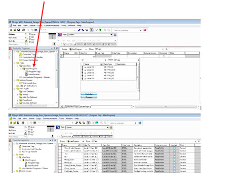
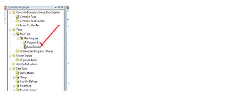
Create a tag. There are multiple ways to create tags. Open either the "Controller" tags or "Main Program" tags window. Tags can be built one at a time as you program, or tags can be created in the Tag Editor. The Tag Editor enables you to create and edit tags using a spreadsheet-like view of the tags. Click on Main Program. Double-click on "Program Tag" and then click on "Edit Tags". Select the first cell and enter the "Tag Name". Select the second cell and enter the "Alias For".
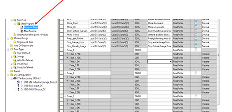
Create a timer. Timers can be connected to each tag name. Setting timing parameters and address time data is necessary. Click and select on "Program Tag" and then click "Edit Tag". Select the first cell and enter "Timers".
Creating a Ladder Diagram Rung
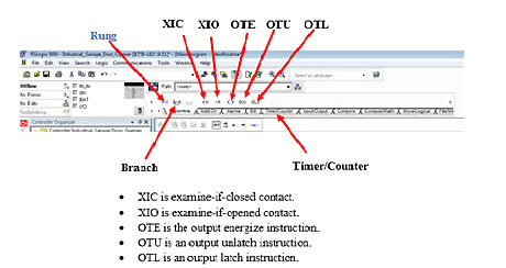
See the "Ladder Diagram Basic Instructions" icon located in the programming toolbar.
Create a ladder diagram for Rung 0. Create a rung that opens and closes the outside door and activates the top limit switch. . Double-click on MainRoutine and then a new window will pop up. The instructions icon is located on top of the new window. Click and drag the Rung instruction icon to the new window. Click and drag the XIC instruction icon into the rung. Highlight the instruction and type Open_Outside_Garage_Door and press ↵ Enter. Click and drag the XIO instruction icon into the rung. Highlight the instruction and type Stop_Outside_Door and press ↵ Enter. Click and drag the XIO instruction icon into the rung. Highlight the instruction and type Top_Limit_Switch and press ↵ Enter. Click and drag the OTE instruction icon into the rung. Highlight the instruction and type Motor_Up and press ↵ Enter. Tenneng 3.png.
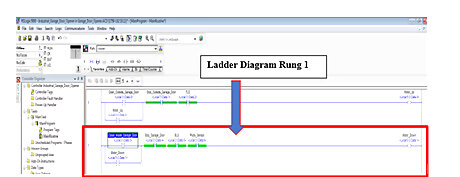
Create a ladder diagram for Rung 1. Create a rung that closes and stops the door and activates the bottom limit switch. The photosensor is used to detect if an object blocks the door while it's closing; if so, it stops closing the door. Click and drag the XIC instruction icon into the rung. Highlight the instruction and type Close_Inside_Garage_Door and press ↵ Enter. Click and drag the XIO instruction icon into the rung. Highlight the instruction and type Stop_Inside_Door and press ↵ Enter. Click and drag the XIO instruction icon into the rung. Highlight the instruction and type Bottom_Limit_Switch and press ↵ Enter. Click and drag the XIO instruction icon into the rung. Highlight the instruction and type Stop_Inside_Door and press ↵ Enter. Click and drag the XIO instruction icon into the rung. Highlight the instruction and type Photo_Sensor and press ↵ Enter. Click and drag the OTE instruction icon into the rung. Highlight the instruction and type Motor_Down and press ↵ Enter. Click and drag the Branch instruction icon and then place it below Close _ Inside_Garage_Door. Highlight the branch instruction icon and type Motor_Down and press ↵ Enter.
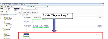
Create a ladder diagram of Rung 2. Create a rung that represents the green light ON while the door opens inside the garage; the light remains ON until the door is completely open and hits the top limit switch. Click and drag the XIC instruction icon into the rung. Highlight the instruction and type Motor_Up and press ↵ Enter. Click and drag the OTE instruction icon into the rung. Highlight the instruction and type Green_Light_Inside_Garage and press ↵ Enter. Click and drag the Branch instruction icon and then place it below Motor_Up. Highlight the branch instruction icon and type Timer_1_TT and press ↵ Enter.
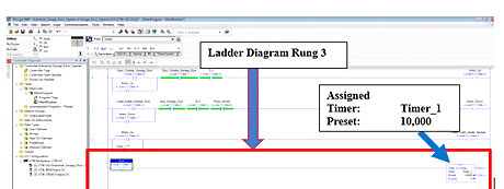
Create a ladder diagram of rung 3. Create a rung that represents the timing (Time on Delay) of the green light to remain ON for extra 10 seconds until it hit the top limit switch. Click and drag the XIO instruction icon into the rung. Highlight the instruction and type Bottom_Limit_Switch and press ↵ Enter. Click and drag TON instruction icon into the rung. The TON is in Timer/Counter instruction. Highlight the TON "Timer" and type Timer_1 and press ↵ Enter. Highlight "Preset" and type 10,000 and press ↵ Enter.
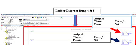
Create a ladder diagram of Rungs 4 & 5. Create rungs that control the timing of red light flasher. Click and drag the XIO instruction icon into the rung 4 and highlight the instruction and type Timer_3.DN and then press ↵ Enter. Click and drag the TON instruction icon into the rung 4. The TON is in Timer/Counter instruction. Highlight TON "Timer" and type Timer_2 and press ↵ Enter. Highlight "Preset" and type 500 and press ↵ Enter. Click and drag the XIO instruction icon into the rung 5 and highlight the instruction and type Timer_2.DN and then press ↵ Enter. Click and drag TON instruction icon into the rung 5. The TON is in Timer/Counter instruction. Highlight TON "Timer" and type Timer_3 and press ↵ Enter. Highlight "Preset" and type 500 and press ↵ Enter.
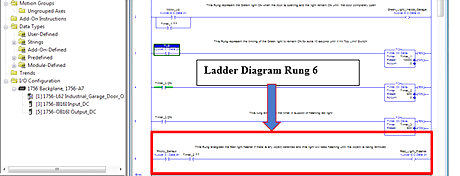
Create a ladder diagram of Rung 6. This rung energizes the red-light flasher if there is an object detected; the light will keep flashing until the object is removed. Click and drag the XIC instruction icon into the rung. Highlight the instruction and type Photo_Sensor and press ↵ Enter. Click and drag the XIC instruction icon into the rung. Highlight the instruction and type Timer_2.TT and press ↵ Enter. Click and drag the OTE instruction icon into the rung. Highlight the instruction and type Red_Light_Flasher and press ↵ Enter.
Test and Run the Program on Off-Line
Test with emulator software to find problems before the software is used in the Control System or Off-Line Run Mode. Click on the Verify All icon to check your program for errors that would prevent the program from testing or running. Once your code is verified, the eee's will disappear from the left side of the rungs.
Click on Off-Line Run Mode located at the left top corner of the program.
Observe the outcome. When the run mode is activated, the processor transfers the status of all the real inputs into the input image table memory. The PLC then begins to scan each rung in the ladder program starting at rung 0. It compares each input element of each rung and sets that rung's output ON or OFF depending on the rung logic.


Comments
0 comment